Wiring for Processing

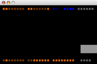
Screenshot from the Wiring for Processing input example.
Overview
Wiring for Processing allows the use of core Wiring functionality from Processing (or any software that can access the serial port). Control basic output devices (e.g. LEDs, DC motors) and read simple sensors (e.g. buttons, photoresistors) without writing any microcontroller code.
Wiring Firmware
Requires Wiring 0002 or later.
A program to allow the control of the Wiring board from the computer using a serial protocol.
Download
: wiring-firmware.zipInstallation
- Unzip the Wiring firmware.
- Move the contained firmware folder into your Wiring sketchbook folder (located by default in My Documents on Windows, Documents on the Mac).
- Connect the Wiring board to the computer.
- Launch Wiring, open the firmware sketch, and hit the verify (play) button.
- Select the appropriate serial port from the Tools | Serial Port menu (on Windows, this is the COM port used by the FTDI driver; on the Mac, it's something like /dev/tty.usbserial-1B1).
- Press the reset button on the Wiring board, then hit the export button in Wiring.
- After the download completes, reset the Wiring board.
Processing Library
Requires Processing 0085 or later.
Download
: wiring-library.zipInstallation
- Unzip the Wiring library.
- Move the contained wiring folder into the libraries subfolder of your Processing application directory.
- Try one of the examples below.
Reference
A quick sample (more complete examples below):
import processing.serial.*;
import org.mellis.wiring.*;

Wiring wiring;

void setup()
{
  wiring = new Wiring(this, "COM4");
  wiring.pinMode(0, Wiring.OUTPUT);
}

void draw()
{
  if (wiring.analogRead(0) > 512)
    wiring.digitalWrite(0, Wiring.HIGH);
  else
    wiring.digitalWrite(0, Wiring.LOW);
}
Currently supported functions from the Wiring API:
- Wiring(parent, device)
- Initializes the Wiring library. For example:
Wiring wiring = new Wiring(this, "COM4"); - pinMode(pin, mode)
- Puts the digital pin in Wiring.INPUT or Wiring.OUTPUT mode.
- digitalWrite(pin, value)
- Write Wiring.HIGH (5 volts) or Wiring.LOW (0 volts) on the digital pin.
- digitalRead(pin)
- Returns the value of the pin, either Wiring.HIGH or Wiring.LOW.
- analogWrite(pin, value)
- Writes an analog value (as a PWM wave) between 0 (always low) and 255 (always high).
- analogRead(pin)
- Returns the value on the analog pin, from 0 (0 volts) to 1023 (5 volts).
Source
: Wiring.java, Makefile.Examples
Example 1: Input
This example demonstrates the use of the Wiring library for receiving input from the Wiring board. To try it, simply paste the code in wiring_in.pde into a new Processing sketch, change the second argument of beginWiring() to the serial device used by Wiring, and run.
Example 2: Output
This example demonstrates the use of the Wiring library for output to the Wiring board. To try it, simply paste the code in wiring_out.pde into a new Processing sketch, change the second argument of beginWiring() to the serial device used by Wiring, and run.
Last updated: 21 July 2005